Let Us Know How We Can Help. We Are Your Dedicated Solutions Provider.

PCB components are the parts that turn a bare circuit board into a working electronic system. They guide, switch, store, and regulate electrical signals and power. A small ceramic capacitor near a processor may steady its supply, while a connector at the board’s edge links it to another device. Each part has a job. Its placement matters, too.
PCB design expert Rick Hartley is known for the reminder, “Current flows in loops.” That principle helps explain why component choice and placement belong together: a resistor, integrated circuit, or power component cannot be evaluated in isolation from the paths around it. This guide explores the main types of pcb components, including active and passive parts, electromechanical devices, and connectors. It also considers how package size, ratings, heat, and board layout affect practical selection.
The labels can seem tidy. Real designs are not always so tidy. A part may fit the schematic but create routing or thermal problems on the board. Designers therefore check datasheets, operating conditions, and manufacturer guidance before committing to a component. These checks reduce avoidable surprises, though they do not replace testing in the intended product. The sections ahead offer a clear starting point for recognizing common components and understanding what each contributes. Some details still depend on the application. That is worth remembering.
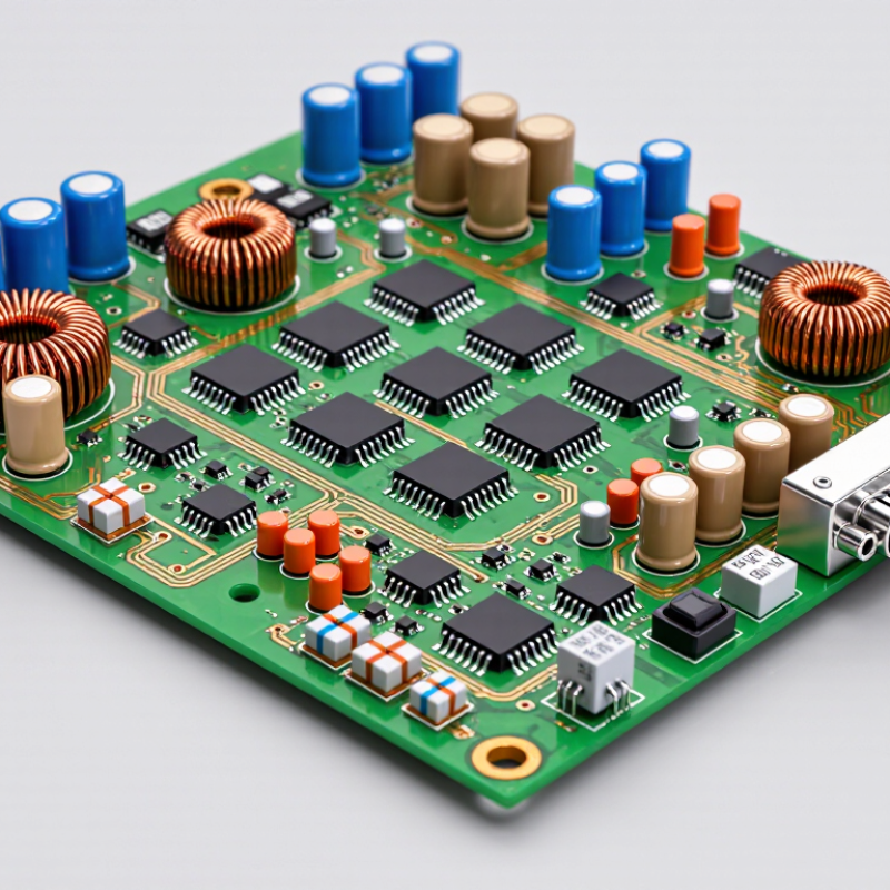
Passive components shape current and voltage without adding energy. Resistors limit current, set bias points, and form voltage dividers. A small resistor near an LED can prevent excessive current. A feedback resistor helps define an amplifier’s gain. Check resistance, tolerance, and power rating; a part can overheat even when its value is correct.
Capacitors store charge and smooth changing voltage. A decoupling capacitor placed close to an IC’s supply pins can reduce brief voltage dips. Capacitance matters, but so do voltage rating, dielectric behavior, and placement. Inductors resist rapid changes in current and store energy in a magnetic field. They appear in filters and switching power supplies, where core saturation and winding resistance affect performance. The schematic is only part of the story. Board layout can change results.
Tips: Place decoupling capacitors near the pins they serve, using short traces. Leave room to check polarity on polarized capacitors. A suitable value can still perform poorly when package choice or layout adds unwanted effects. Test the assembled board under realistic load, not just on paper.
Active components control or amplify electrical signals; they need operating power to do so. A diode usually conducts in one direction, making it useful for rectification and reverse-polarity protection. Some diodes emit light. Others help clamp voltage spikes near a sensitive input. A transistor can switch a motor, regulate a supply, or amplify a small sensor signal. On a real board, its heat and switching speed matter as much as its schematic symbol.
Integrated circuits, or ICs, combine many semiconductor devices in one package. A small controller may read sensor inputs and drive outputs, while an amplifier IC conditions a weak signal. The package’s pinout, supply voltage, and nearby decoupling capacitors deserve careful checks. That detail is easy to miss. Still, a schematic can make a circuit look cleaner than it behaves on the bench, especially when traces are long or loads switch quickly.
Industry figures show the scale behind these parts. The Semiconductor Industry Association reported global semiconductor sales of $627.6 billion in 2024, up 19.1%, based on data from the World Semiconductor Trade Statistics organization. WSTS forecast $697.1 billion for 2025, an 11.2% increase (WSTS, Fall 2024 forecast). These figures describe chip sales, not PCB component counts. For board designers, the practical lesson is narrower: active components are increasingly capable, but their electrical limits still shape reliability, heat, and layout choices.
Electromechanical components connect electronic signals with physical actions or measurements. A switch may start a device, select a mode, or detect a cover opening. On a PCB, check its footprint, actuator clearance, and expected number of operations. A tiny tactile switch can feel precise, yet its contacts may produce several rapid transitions when pressed. Software debounce helps, but it should match the circuit’s timing needs. A click is useful.
Relays use an electrical coil to move contacts, allowing a low-voltage control signal to switch a separate load. Their coils can create voltage spikes when switched off, so a suitable suppression component, such as a flyback diode for a DC coil, may be needed. Check coil current, contact ratings, and PCB spacing against the actual application. A relay is not automatically safe just because its contacts are physically separated from its coil.
Sensors turn conditions such as temperature, light, or position into electrical signals. Their readings depend on placement: a temperature sensor beside a hot power component may report the board’s heat, not the surrounding air. Long sensor traces can also pick up noise, so routing and filtering deserve attention. Calibration is sometimes necessary. It is easy to assume the first reading is correct; in practice, testing the assembled board under real operating conditions often reveals small errors.
The chart compares poles—the number of independently switched circuits—in representative SPST, DPDT, and SPDT configurations. A limit switch is a mechanically actuated sensor; available configurations vary by component.
Interconnection components create the electrical and mechanical paths between a PCB and other parts of a device. Board connectors support removable cables or modules, while terminals provide points for clamping or soldering wires. PCB sockets accept components that may need replacement or testing. Each choice affects assembly time, service access, and reliability.
The market reflects their broad importance. Grand View Research valued the global connector market at USD 84.1 billion in 2023 and projected a 5.3% compound annual growth rate from 2024 to 2030. This figure covers many connector applications, not PCB parts alone. On a control board, a detachable connector can simplify maintenance, but its contacts need enough retention for vibration. A terminal block may handle field wiring better, though it takes more board space. Small sockets can look convenient; they may still loosen after repeated handling. That trade-off deserves attention.
Tips: Check current, voltage, wire size, pitch, and expected mating cycles against the component datasheet. Leave room for fingers and tools near terminals. Then inspect the assembled board under realistic vibration and temperature conditions.
Protection and thermal components manage faults that ordinary circuit parts cannot handle alone. A fuse opens when current exceeds its rating for long enough. Its voltage rating and interrupting capacity matter too. Match its response time to the circuit; a fast fuse may nuisance-trip during startup. A fuse cannot prevent every damaging surge.
Suppressors, such as TVS diodes or varistors, limit brief voltage spikes. Place them close to the connector or vulnerable circuit, with a short path to ground. Long traces add inductance and can reduce their effectiveness. Check clamping voltage and surge-energy ratings against the parts being protected. Small details matter.
Heat sinks move heat away from hot components, while copper planes and thermal vias can spread it through the board. Check airflow, mounting space, and the thermal interface, not just the sink’s size. A larger sink may still perform poorly in a cramped enclosure. Heat matters. One common design miss is treating protection and cooling as separate tasks: a suppressor can heat during a surge, and a fuse can warm under sustained load. A tidy layout can still behave poorly when real operating conditions are overlooked.