Let Us Know How We Can Help. We Are Your Dedicated Solutions Provider.

How to Choose Circuit Board Components for Global Sourcing?
Choosing circuit board components for global sourcing is not merely a price comparison exercise. It is a practical decision involving performance, availability, traceability, compliance, and long-term risk. A component that saves eight cents today may create weeks of delay tomorrow.
John W. Mitchell, former president and CEO of IPC, said, “Quality and reliability are designed into products; they cannot be tested in afterward.” This principle remains important when reviewing resistors, capacitors, connectors, ICs, and power modules across international suppliers. Buyers should examine the manufacturer’s datasheet, lifecycle status, tolerance, operating temperature, moisture sensitivity level, and approved alternatives. Supplier audits also matter. A polished website proves very little.
Real sourcing work often begins with a detailed bill of materials. Part numbers must match exactly. Packaging, date codes, factory location, and certificates should be checked before shipment. RoHS and REACH documentation may be necessary, depending on the destination and product category. Counterfeit risks increase when brokers offer unusually low prices. That offer deserves questions, not excitement.
Lead times can change suddenly. Geopolitical events, capacity shortages, and currency movement may affect landed cost. Dual sourcing helps, but it can introduce small electrical differences. Those differences are easy to overlook. I have seen sourcing plans fail because an “equivalent” capacitor had different voltage derating behavior. Careful engineers verify samples under real operating conditions.
The best global sourcing strategy is therefore cautious, documented, and flexible. It may not produce the cheapest first quotation. It usually produces fewer surprises.
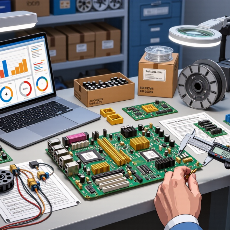
Table of Contents
[Hide]
Map Component Ratings to IPC-2221, Voltage, Current, and Thermal Limits
How to Choose Circuit Board Components for Global Sourcing?
Global sourcing starts with ratings, not part numbers. The WSTS Spring 2024 forecast valued worldwide semiconductor sales at $588 billion for 2024, a 13.1% annual increase. That growth increases substitution risk. Map every candidate component against voltage, current, temperature, and insulation requirements. For a 24 V control board, record continuous voltage, switching peaks, inrush current, and the 45°C maximum ambient temperature. A capacitor rated for 25 V may pass nominal testing, yet offer little surge margin. Choose a higher voltage rating when transients are credible.
Use IPC-2221B to check conductor geometry and spacing. Its current-carrying method links copper cross-sectional area with allowable temperature rise. IPC-2152 test curves provide a more practical validation path, especially for internal layers and dense routing. Do not treat a trace calculator as laboratory proof. Measure a prototype under worst-case load. For insulation, IEC 60664-1 connects clearance and creepage to working voltage, pollution degree, and overvoltage category. These conditions differ between a sealed control cabinet and an exposed industrial enclosure.
Thermal limits need equal attention. Compare maximum junction temperature, case temperature, and board temperature, then apply derating for airflow, copper spreading, and nearby heat sources. A component passing at 25°C may fail near 70°C. That mistake is common. Datasheets also vary in test conditions, so compare like with like. My own selection reviews sometimes overvalue nominal efficiency and undervalue connector heating. Rechecking those assumptions is necessary.
| Component Category | Typical Rating Range for Design Screening | Recommended Design Margin | PCB and IPC-2221 Mapping | Voltage, Current, and Thermal Checks | Global Sourcing Verification Data |
|---|---|---|---|---|---|
| Component-Level Selection and Board-Level Constraints | |||||
| Fixed Resistor |
Resistance: 1 Ω to 10 MΩ Power: 0.063 W to 5 W Working voltage: commonly 50 V to 500 V, depending on package |
Operate at no more than 50% to 70% of the rated power where long life and reduced temperature rise are required. | IPC-2221 does not establish the resistor's electrical rating. It supports land-pattern, spacing, conductor, and thermal-layout decisions around the part. | Check pulse overload, maximum working voltage, ambient temperature, resistor temperature rise, and PCB copper temperature near high-power parts. | Confirm resistance tolerance, temperature coefficient, power derating curve, pulse capability, package size, flame rating, moisture sensitivity, and approved test documentation. |
| Multilayer Ceramic Capacitor |
Capacitance: 10 pF to 100 µF Rated voltage: 6.3 V to 3 kV Common packages: 0402 to 2220 |
Use a voltage rating at least 1.5 to 2 times the maximum continuous applied voltage, with additional allowance for transients and DC-bias capacitance loss. | Maintain appropriate surface spacing and pad geometry. For elevated voltages, use IPC-2221 insulation-spacing guidance together with the applicable safety standard and pollution environment. | Check DC-bias derating, ripple-current heating, dielectric temperature range, piezoelectric noise, surge voltage, and board flexure risk. | Verify dielectric type, capacitance under operating bias, tolerance, aging behavior, termination material, soldering profile, and availability in the required case size. |
| Aluminum or Polymer Capacitor |
Capacitance: 1 µF to several thousand µF Rated voltage: 6.3 V to 500 V Ripple current: typically specified at a reference temperature and frequency |
Select at least 20% voltage headroom and use the manufacturer's ripple-current and temperature-life curves for the actual operating conditions. | Provide clearance for the can, vent, and body. Use short, wide current paths and consider heat transfer from nearby regulators, transformers, or power semiconductors. | Check ripple-current heating, equivalent series resistance, lifetime at actual hot-spot temperature, polarity, reverse voltage, and inrush current. | Confirm endurance rating, temperature class, impedance, ripple-current test conditions, storage requirements, polarity marking, and mechanical retention. |
| Diode or Rectifier |
Repetitive peak reverse voltage: 20 V to 6.5 kV Average forward current: 0.1 A to several hundred amperes Forward voltage: approximately 0.3 V to 3.5 V, depending on technology and current |
Use a reverse-voltage rating of at least 1.5 times the highest repetitive circuit voltage when transient control is well defined; increase the margin for uncontrolled transients. | Use adequate copper area, thermal vias, creepage, and clearance. High-current diode pads should be connected to conductors sized for the calculated RMS or average current. | Calculate conduction and switching losses, junction temperature, surge current, reverse-recovery behavior, and heat spreading through the package and PCB. | Verify polarity marking, surge rating, thermal resistance, repetitive and nonrepetitive current ratings, qualification temperature range, and package compatibility. |
| MOSFET or Power Transistor |
Drain-source voltage: 20 V to 1.7 kV Continuous drain current: 1 A to more than 300 A Power dissipation: package- and heatsink-dependent |
Keep normal voltage below 70% to 80% of the rated voltage unless transient control and qualification testing justify a different value. Design junction temperature below 125°C where long life is important. | Use wide copper regions, thermal vias, controlled gate loops, suitable creepage and clearance, and a thermal path that is consistent with the package land pattern. | Evaluate conduction loss, switching loss, gate-drive voltage, avalanche energy, safe operating area, junction-to-case resistance, and junction-to-ambient resistance. | Confirm RDS(on) at the actual gate voltage and temperature, total gate charge, switching parameters, avalanche rating, thermal characteristics, qualification level, and package source options. |
| Integrated Circuit |
Supply voltage: commonly 1.0 V to 24 V Operating current: microamps to several amperes I/O voltage tolerance: device-specific |
Keep supply voltage within the specified operating range, including tolerance, ripple, startup overshoot, and load-transient conditions. Do not use absolute-maximum values as operating targets. | Follow the component land pattern and thermal recommendations. Use controlled impedance, reference planes, decoupling placement, and spacing appropriate to the signal and voltage class. | Check total power, junction temperature, self-heating, input overshoot, output-current limits, latch-up conditions, ESD sensitivity, and thermal-pad solder coverage. | Verify electrical characteristics over temperature, package outline, moisture sensitivity level, reflow profile, firmware or configuration compatibility, and long-term lifecycle status. |
| Connector or Terminal Block |
Contact current: approximately 0.5 A to 100 A or more Working voltage: approximately 30 V to 1 kV Contact resistance: commonly below 50 mΩ for power contacts |
Apply the specified derating for the number of energized positions, ambient temperature, wire size, mating cycles, and enclosure conditions. | Apply creepage and clearance requirements, mechanical keep-outs, mounting strength, plated-hole dimensions, and copper-area requirements for the connector current. | Check contact temperature rise, terminal torque, insertion and extraction forces, vibration, wire heating, dielectric withstand, and accidental short-circuit exposure. | Verify pitch, pin count, mating compatibility, current rating test method, voltage category, flammability rating, materials, locking method, and regional safety documentation. |
| Fuse or Resettable Protection Device |
Rated current: approximately 50 mA to 100 A Voltage rating: commonly 12 V to 1.5 kV Interrupt rating: from hundreds of amperes to many kiloamperes, depending on type |
Select the nominal current above the continuous operating current but below the safe capacity of the wiring, PCB conductor, connector, and protected load. | Provide the recommended pad geometry and a copper path that does not bypass the protection device. Maintain spacing suitable for the maximum fault voltage. | Check cold resistance, time-current curve, ambient-temperature derating, prospective fault current, interrupt rating, inrush tolerance, and post-fault temperature. | Confirm one-time or resettable operation, agency approvals, fault-test conditions, replacement method, marking, package compatibility, and supply continuity. |
| Inductor or Transformer |
Inductance: approximately 100 nH to 100 mH Rated current: milliamperes to hundreds of amperes Insulation ratings: application-dependent, often 50 V to several kV |
Keep continuous current below the thermal rating and peak current below the saturation or energy limit. A 20% to 30% current margin is commonly used for preliminary selection. | Consider magnetic-field coupling, creepage, clearance, copper loss, thermal vias, component height, and spacing from sensitive analog or high-speed circuits. | Check saturation current, RMS heating current, core loss, winding resistance, temperature rise, insulation system, leakage inductance, and switching frequency. | Verify inductance tolerance under bias, impedance curve, shielding, insulation class, winding configuration, operating temperature, acoustic behavior, and mechanical retention. |
| PCB Copper Trace or Plane | Example screening case: 35 µm copper, 1.0 mm trace width, approximately 10°C allowable temperature rise. | Use the IPC-2221 current-capacity relationship as an initial estimate only. Add margin for copper roughness, etching variation, vias, connectors, ambient temperature, and localized heating. | IPC-2221 conductor sizing uses conductor cross-sectional area and allowable temperature rise. External and internal conductors have different empirical constants; internal layers generally dissipate heat less effectively. | For the example geometry, a first-pass IPC-2221 calculation is approximately 2.4 A for an external trace and approximately 1.2 A for an internal trace at a 10°C rise. Final values require validation because layout and thermal conditions change the result. | Specify copper weight, finished thickness, minimum width, impedance requirements, via current capability, plating thickness, temperature rise limit, and fabrication tolerances. |
| Electrical Spacing and Thermal Design Rules | |||||
| Low-Voltage Power Nets | Typical design range: below 60 V DC, although the applicable safety classification depends on the equipment and installation environment. | Keep sufficient margin for supply tolerance, load dump, hot-plug events, switching overshoot, and abnormal operating conditions. | Use IPC-2221 spacing guidance as a baseline and apply the relevant product-safety standard where personnel access, pollution degree, insulation type, or mains connection is involved. | Check voltage drop, conductor heating, connector heating, transient amplitude, and dielectric withstand between adjacent nets. | Document the operating voltage, maximum fault voltage, insulation requirement, environmental pollution level, altitude, and test method. |
| High-Voltage or Mains-Related Nets | Common equipment ranges include 120 V AC, 230 V AC, and rectified bus voltages above 300 V DC; exact requirements depend on the product category. | Do not select spacing from voltage alone. Include working voltage, repetitive peak voltage, transient overvoltage, pollution degree, material group, altitude, and insulation system. | Use IPC-2221 for general PCB design practice, then verify creepage and clearance against the applicable safety standard. Surface spacing and through-insulation spacing are separate requirements. | Check dielectric withstand, insulation resistance, creepage contamination, slotting requirements, arc risk, component body spacing, and thermal stress during fault conditions. | Require documented safety approvals, insulation-system data, flammability classification, production dielectric testing, and region-specific compliance evidence. |
| Thermal Management | Typical design targets: component junction temperature below 100°C to 125°C for long-life designs, subject to the component's specified maximum. | Maintain a practical thermal margin below the absolute maximum junction, case, or board temperature. Use the worst-case ambient and maximum electrical load. | Use copper spreading, thermal vias, heat sinks, airflow, component spacing, and board orientation. IPC-2221 supports design methodology but does not replace package-specific thermal data. | Estimate total loss using P = I²R for resistive paths and P = V × I for semiconductor conduction paths, then calculate junction temperature from the applicable thermal resistance. | Collect thermal resistance values, derating curves, maximum case temperature, reflow limits, environmental temperature range, and test results from the intended source. |
| Engineering note: IPC-2221 provides PCB design guidance and empirical conductor-sizing methods; it does not replace the component manufacturer's electrical, thermal, safety, or reliability specifications. Final approval should use worst-case voltage, current, temperature, transient, spacing, manufacturing-tolerance, and environmental conditions. | |||||
Related Posts
-
Who Are the Top 10 PCB Design Companies in China?
-
What Are the Top Types of Printed Circuit Boards?
-

10 Best PCB Fabrication Companies for Global Buyers
-

Top 10 Printed Circuit Board Manufacturers Worldwide
-
10 PCB Manufacturing Tips for Global Buyers?
-

Why Is a Circuit Board Essential for Modern Electronics?