Let Us Know How We Can Help. We Are Your Dedicated Solutions Provider.

How to Choose the Right PCB Components?
Choosing the right pcb components is not simply a matter of matching values on a schematic. Each choice affects board size, power use, heat, reliability, and assembly. A resistor may meet its nominal rating yet run too close to its limit inside a warm enclosure. A capacitor may fit the footprint but lose effective capacitance under operating voltage. Small details matter.
A sound selection process starts with the circuit’s electrical requirements, then checks package dimensions, tolerances, temperature range, and expected operating life. Datasheets provide essential limits, but they do not replace careful review of the actual application. Consider whether parts are available from dependable suppliers and whether alternate components can be qualified without changing the design. That is not always obvious. A cheaper part can bring longer lead times or tighter operating margins, while a premium specification may add cost without meaningful benefit.
This guide explains how to compare component specifications, assess environmental and manufacturing needs, and make trade-offs with evidence. In practical design reviews, the most useful questions are often specific: How hot will this regulator get? Can the assembler place this package reliably? Will the chosen connector withstand repeated use? There is no perfect shortlist, and that can be frustrating. Still, documenting assumptions and checking them against datasheets, simulations, and prototype measurements makes decisions easier to revisit. The goal is not to select the most impressive parts, but to build a PCB that performs consistently in its real operating conditions.
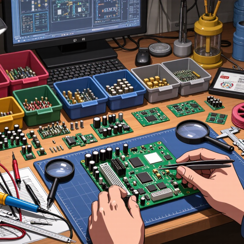
Table of Contents
[Hide]
Define the PCB’s Electrical, Thermal, and Environmental Requirements
Before selecting PCB components, translate the board’s job into measurable limits. Record supply voltage, expected current, signal frequency, and allowable voltage drop. A regulator carrying 1.5 amperes needs different copper and thermal support than a low-current sensor circuit. Check peak conditions too, not just normal operation. Brief startup surges can expose a weak design.
Heat needs a real path to escape. Estimate component power, then consider copper area, nearby heat sources, enclosure airflow, and the board’s orientation. A component rated for a high junction temperature may still run too hot on a compact board. Leave room for thermal vias or a wider copper pour where testing supports it. Calculations help, but a crowded layout can behave differently than expected.
Environmental requirements shape both parts and materials. Note the operating temperature range, humidity, dust, vibration, and possible condensation. A device near a sunny window may face heat cycles; one inside a sealed enclosure may trap heat. Choose component ratings with margin, and verify them against datasheets rather than relying on a quick catalog filter. Measure a prototype under realistic conditions. It may reveal that an assumption was too optimistic. Revisit the limits when test results disagree, and document why each critical rating was chosen.
How to Choose the Right PCB Components? - Define the PCB’s Electrical, Thermal, and Environmental Requirements
Use this table as a practical starting point for component selection. The figures are representative design checks, not universal specifications; confirm limits, derating guidance, and test conditions in each component’s datasheet.
| Component type | Electrical requirements | Thermal requirements | Environmental requirements | Selection checks |
|---|---|---|---|---|
| Fixed resistor | Choose resistance and tolerance for the circuit function. Check maximum working voltage, pulse capability, and power rating; for example, a 0.25 W part should not be assumed to dissipate 0.25 W at every ambient temperature. | Estimate dissipation using P = I²R or P = V²/R. Apply the datasheet’s power derating curve and check the resistor’s maximum operating temperature. | Confirm the rated operating-temperature range, moisture resistance, and suitability for expected vibration or contamination. | Check tolerance, temperature coefficient, package size, voltage limit, pulse rating, and power margin at the actual local ambient temperature. |
| Multilayer ceramic capacitor | Select capacitance, tolerance, rated voltage, and dielectric. Account for capacitance loss under DC bias, especially with high-capacitance, small-package parts. | Check temperature-dependent capacitance and dielectric limits. For high ripple current or switching use, verify self-heating and dissipation requirements. | Match the operating-temperature range to the application and consider humidity, board flex, and mechanical stress. Flexible-termination options may help in high-strain locations. | Check effective capacitance at operating bias and temperature, voltage derating, ripple conditions, package size, and cracking risk near board edges or mounting points. |
| Electrolytic capacitor | Verify capacitance, voltage rating, polarity, ripple-current rating, ESR, and expected transient voltage. Use the specified frequency and temperature conditions when comparing ripple ratings. | Estimate internal heating from ripple current and ESR. Operating temperature strongly affects service life; use the manufacturer’s life-estimation method and actual hot-spot conditions. | Check rated temperature, storage limits, humidity exposure, and whether the application’s expected service life is compatible with the capacitor’s life rating. | Allow voltage margin, check ripple-current margin and ESR, confirm polarity and footprint, and assess lifetime at the expected temperature profile. |
| Integrated circuit | Confirm supply-voltage range, input thresholds, output drive, logic compatibility, quiescent current, timing, and absolute maximum ratings. Absolute maximum ratings are not normal operating targets. | Estimate power dissipation and junction temperature using the applicable thermal resistance or thermal characterization data. PCB copper area and airflow can materially affect results. | Choose an operating-temperature grade that covers the expected ambient range. Check moisture sensitivity, ESD requirements, and package handling or storage conditions. | Verify operating limits across supply and temperature, package thermal data, startup behavior, pin compatibility, and any required PCB layout or heat-spreading guidance. |
| MOSFET | Check drain-source voltage, gate-drive voltage, on-resistance at the actual gate voltage, current, safe operating area, and switching losses. Current ratings depend on test conditions and cooling. | Estimate conduction and switching losses, then calculate junction temperature using the thermal path available in the finished PCB. Check transient thermal impedance for pulsed loads. | Confirm operating-temperature limits and robustness against expected voltage transients, humidity, and contamination-related leakage paths. | Use voltage and current margins appropriate to the circuit, verify the safe operating area, inspect gate-charge requirements, and follow PCB copper and thermal-pad guidance. |
| Rectifier or TVS diode | For rectifiers, check reverse voltage, forward current, surge current, and leakage. For TVS devices, match stand-off voltage, breakdown behavior, clamping voltage, and pulse-energy requirements to the protected circuit. | Check forward-loss heating, surge-pulse derating, junction-temperature limits, and the influence of PCB copper area on heat dissipation. | Confirm operating-temperature range and ensure the protection device remains suitable under expected humidity, contamination, and transient conditions. | Compare clamping voltage with the protected circuit’s limits at the specified pulse current; verify pulse waveform, duration, repetition, and layout inductance. |
| PCB connector | Verify rated voltage and current per contact, contact resistance, insulation resistance, and clearance or creepage requirements for the working voltage and pollution conditions. | Check contact and terminal temperature-rise limits. Apply current derating when multiple adjacent contacts are loaded or airflow is restricted. | Match the temperature range, mating-cycle rating, vibration resistance, and any required protection against dust, moisture, or corrosive atmosphere. | Confirm wire or PCB termination compatibility, pin assignment, retention, plating requirements, and current rating under the actual number of loaded contacts. |
| Crystal or oscillator | Check frequency, tolerance, stability, load capacitance (for a crystal), output level (for an oscillator), startup behavior, and drive-level limits. | Verify frequency stability over the operating-temperature range and avoid exceeding a crystal’s specified drive level, which can affect reliability and frequency accuracy. | Select a temperature range and aging performance appropriate to the operating environment; consider vibration and shock sensitivity where relevant. | Confirm the circuit’s load-capacitance calculation, frequency accuracy budget, startup margin, package footprint, and placement guidance near the clock pins. |
Before release, validate the chosen parts against the complete datasheets, worst-case circuit calculations, PCB thermal conditions, and the product’s environmental and reliability test plan.
Related Posts
-
Why Are PCB Components Important for Global Buyers?
-

How to Choose the Right Wire Harness Assembly Supplier?
-
How to Create a Circuit Board for Your Electronics Projects?
-

Top 10 Printed PCB Board Types for Your Electronics Projects
-

2025 Guide: How to Master Circuit Board Design for Optimal Performance
-

How to Choose the Right Electronic Board Design Supplier?