What Are the Top Types of Printed Circuit Boards?
Choosing a printed circuit board begins with the product’s electrical, mechanical, and thermal demands. A wearable sensor needs flexibility and light weight. A server board needs controlled impedance, dense routing, and reliable heat management. The best type depends on the application.
Paul Eisler, widely recognized as a pioneer of printed circuit technology, described the principle clearly: “The printed circuit is a means of wiring electrical circuits by printing the wiring on an insulating base.” His explanation still fits modern boards, although today’s designs use advanced materials, laser drilling, and tightly controlled fabrication processes.
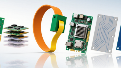
This guide examines the top types of printed circuit boards, including single-sided, double-sided, multilayer, rigid, flexible, and rigid-flex boards. It also considers HDI and metal-core designs, which support compact electronics and demanding thermal conditions. Each category has practical strengths and limitations. Single-sided boards can reduce cost and simplify assembly. Multilayer boards save space but require stricter manufacturing control. Flexible boards bend around hinges, yet repeated movement can expose weaknesses if the design is careless.
Real production results depend on more than board type. Material selection, copper thickness, via design, surface finish, and inspection standards all matter. A technically impressive layout may still fail during assembly. That distinction is easy to overlook.
There is no universal winner. The right choice balances performance, reliability, manufacturability, and budget. Some classifications also overlap, which can make comparisons less precise. That is worth remembering.
PCB Classification by Layer Count and Structure
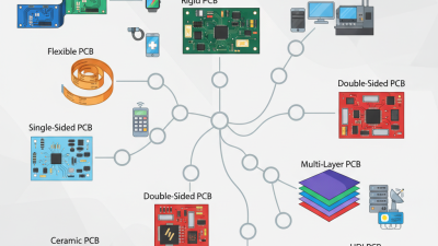
Printed circuit boards are commonly classified by layer count and physical structure. A single-sided board carries copper on one surface. It suits simple controls, lighting, and low-density wiring. A double-sided board adds plated through-holes and routing on both faces. It saves space but demands tighter registration and reliable hole plating. Multilayer boards stack copper planes with dielectric material. Four to eight layers often support power distribution, controlled impedance, and dense digital routing. Advanced computing designs may use far more layers. However, extra layers increase drilling, lamination, inspection, and repair costs.
Structure matters as much as layer count. Rigid boards provide stable support for connectors and heat-generating components. Flexible boards bend around hinges and narrow enclosures. Rigid-flex designs combine both and can reduce cable assemblies and failure points. HDI boards use microvias and fine traces for compact, high-density layouts. IPC’s 2024 PCB Technology Roadmap identifies HDI, advanced packaging, and denser interconnects as continuing manufacturing priorities. Prismark’s 2024 market data estimated global PCB sales at approximately US$73 billion, driven by automotive, communications, computing, and industrial equipment. Still, growth does not make every complex stack-up sensible. Designers should verify material availability, thermal paths, impedance targets, and test access. Layer estimates can fail when return-current paths are ignored. That mistake is easy to miss. A six-layer board with disciplined grounding may outperform a ten-layer design with poor partitioning.
Rigid, Flexible, and Rigid-Flex Board Designs
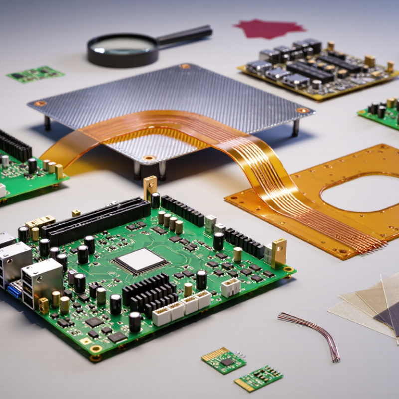
Rigid, flexible, and rigid-flex boards serve different mechanical and electrical demands. Rigid boards remain cost-effective for stable assemblies, such as control modules and power supplies. Flexible boards bend around hinges, cameras, and compact connectors. Rigid-flex designs combine both structures, reducing cable count and assembly points. That integration can improve reliability, but it also raises design and inspection demands.
Fortune Business Insights estimates the global PCB market reached about USD 81.74 billion in 2023. Its report projects continued growth through 2032, driven partly by automotive electronics, medical devices, and communication equipment. IPC-2221 and IPC-6013 provide useful design and qualification guidance for rigid and flexible constructions. In practice, bend radius, copper thickness, adhesive selection, and thermal cycling often decide whether a flexible circuit survives. A small routing mistake can become a crack after thousands of bends. The simplest layout is not always the safest.
Tips: Define the bend zone before routing traces. Keep vias away from repeated flex areas. Ask the fabricator for tested stack-up data, not only a drawing. I have seen teams choose rigid-flex to save space, then discover that tooling and repair access were underestimated. That is a useful reminder: compactness needs evidence. Prototype testing should include actual bending, vibration, temperature changes, and connector movement. A laboratory result may still miss field behavior.
Single-Sided, Double-Sided, and Multilayer PCBs
What Are the Top Types of Printed Circuit Boards?
Single-Sided, Double-Sided, and Multilayer PCBs
Single-sided PCBs place copper traces on one surface. They suit simple controls, lighting modules, and low-cost consumer devices. Double-sided PCBs use copper on both surfaces. Plated through-holes connect the layers and support denser routing. IPC’s 2024 North American PCB Statistical Program reported continued demand pressure across standard board segments. Cost still matters.
Multilayer PCBs stack several copper layers with insulating material between them. They support compact computers, medical instruments, and advanced control systems. A four-layer design can separate power, ground, and signal paths more effectively. Higher layer counts improve routing options, but they increase drilling, registration, testing, and repair challenges. A 2024 market analysis from Fortune Business Insights estimated the global PCB market at about 89.7 billion dollars in 2023. That growth reflects rising electronic content, not unlimited design freedom. The boundary is not always neat. A poorly planned multilayer board can perform worse than a careful double-sided design.
Tips: Choose the fewest layers that meet routing, thermal, and signal requirements. Check trace width, hole size, and material limits with your fabricator early. IPC-2221 design guidance remains useful, but real production feedback matters more than a perfect drawing. Leave room for inspection. Tiny defects become expensive surprises.
Specialized PCB Types for High-Frequency and High-Density Use
High-frequency and high-density applications need more than a standard circuit board. They require controlled impedance, stable dielectric behavior, and precise fabrication. Common choices include PTFE-based laminates, ceramic-filled materials, low-loss laminates, and HDI boards with microvias. Rigid-flex designs also help when equipment has limited space or repeated movement.
Signal loss matters. At high frequencies, copper roughness, connector geometry, and dielectric variation can distort fast signals. Material selection should therefore consider dissipation factor, dielectric constant, thermal stability, and moisture absorption. IPC’s 2024 Technology Roadmap highlights finer features, higher layer counts, and greater interconnect density as continuing industry requirements. In practice, a low-loss material can still fail when the stack-up is poorly engineered.
According to Fortune Business Insights, the global PCB market was valued at approximately US$89.7 billion in 2023, reflecting strong demand across connected electronics. High-density interconnect technology supports compact routing through laser-drilled microvias and sequential buildup layers. These structures save space, but they increase process sensitivity. Small errors compound. IPC design guidance stresses trace geometry, spacing, and fabrication tolerances because electrical performance depends on manufacturing discipline.
I have seen designers focus heavily on laminate selection and overlook return-current paths. That is an expensive weakness. Simulation, test coupons, and supplier capability reviews should be part of the design process. The perfect material does not rescue an unrealistic fabrication plan.