Why Is a Circuit Board Important in Electronics?
A circuit board is easy to overlook. It sits inside a phone, router, or washing machine, holding tiny components in place. Yet without its carefully arranged paths, those parts could not reliably exchange power and signals. A circuit board acts as both a physical platform and an electrical map. Copper traces connect chips, resistors, and connectors, while the board’s layers help route signals through limited space.
Its importance becomes clearer when a device behaves unpredictably. A loose connector, damaged trace, or poorly managed heat can interrupt operation, even when the main chip still works. Board layout also affects signal quality, repair options, and how consistently a product performs. These details matter to designers, technicians, and anyone trying to understand what is inside everyday electronics. Small, but essential.
The board is not magic, and it does not guarantee a reliable product on its own. Component choice, manufacturing quality, testing, and operating conditions all play a part. In practice, a neat-looking board may still hide difficult trade-offs between cost, size, heat, and serviceability. That is worth remembering. Looking closely at a circuit board offers a practical way to see how electronic systems are connected—and why careful design matters long after a device leaves the factory.
Define the Circuit Board: IPC-2221 Guides Interconnect Design
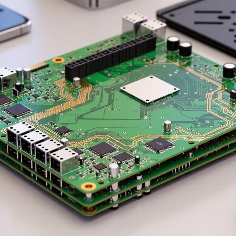
A circuit board is the physical platform that supports components and connects them through patterned copper. It is more than a mounting surface. Copper traces carry signals and power between pads, while insulating material separates conductive paths. IPC-2221B, the Generic Standard on Printed Board Design, provides a framework for planning those interconnections. It addresses factors such as conductor width, spacing, electrical clearance, and board construction. These choices affect whether a compact layout can handle its voltage, current, and operating environment. The standard guides design; it does not replace engineering judgment or product-specific testing.
The scale of the industry makes careful design consequential. IPC’s World PCB Production Report estimated global printed circuit board production at about US$81.9 billion in 2022. That is substantial. On a real board, a narrow trace may run beside a power path, with only a slim gap between them. IPC-2221 helps designers evaluate that geometry against electrical and manufacturing needs before fabrication. Still, a standard cannot catch every layout weakness. A rule-compliant board can remain difficult to assemble or troubleshoot, and I have seen small routing compromises create avoidable rework. Designers should document assumptions and review critical paths with the fabricator.
Support Components: FR-4 Glass-Epoxy Is a Widely Used Board Material
A circuit board must support components while keeping their electrical connections stable. FR-4 does both. It is made from woven glass fabric bonded with flame-retardant epoxy resin. The glass cloth helps the board resist bending; the resin holds the layers together and insulates copper traces. Look closely at a green board: the green color usually comes from its solder mask, not the FR-4 core. Many standard FR-4 grades list a glass-transition temperature near 130°C, but the value varies by formulation. IPC-4101 defines requirements for laminate materials and recognizes different classes. One number does not describe every grade.
FR-4 is popular because it offers a practical balance of stiffness, electrical insulation, availability, and cost. Its flame performance also matters inside compact devices. Under UL 94, a V-0 rating limits afterflame time to 10 seconds per specimen and 50 seconds total across the specified ten flame applications. That is a test result, not a promise that a board cannot burn. Still, standard FR-4 may be a poor fit for very high-frequency signals or repeated high temperatures. Heat can stress the laminate, and signal loss can become important. A board may look solid and still need a different material for its job.
Why Is a Circuit Board Important in Electronics? - Support Components: FR-4 Glass-Epoxy Is a Widely Used Board Material
| Dimension |
Typical Information |
Why It Matters in Electronics |
| Circuit board role |
A printed circuit board (PCB) holds components in position and provides conductive paths between them. |
It creates an organized, repeatable structure for assembling and connecting an electronic circuit. |
| Common support material |
FR-4 is a glass-fiber-reinforced epoxy laminate widely used as a rigid PCB base material. |
The glass reinforcement provides mechanical support, while the epoxy resin binds the laminate and electrically insulates its conductive layers. |
| Typical relative permittivity |
Approximately 4.2–4.8 at around 1 MHz for many FR-4 laminates; the value varies with formulation, frequency, and test method. |
Permittivity affects signal propagation and impedance, so it is considered when designing high-speed traces and controlled-impedance circuits. |
| Glass-transition temperature |
Common FR-4 grades have glass-transition temperatures roughly in the 130–180 °C range; specific grades can fall outside this range. |
This temperature indicates where the resin changes behavior. Higher-temperature processes and applications may require a suitable higher-Tg material. |
| Thermal conductivity |
Typical through-thickness values are around 0.3–0.4 W/(m·K), with variation by laminate construction. |
FR-4 conducts heat relatively poorly compared with metals, so power components may need copper planes, thermal vias, or separate heat-management measures. |
| Common board thickness |
About 1.6 mm is a widely used nominal thickness, although thinner and thicker boards are also manufactured. |
Thickness affects rigidity, enclosure fit, connector compatibility, and some electrical characteristics. |
| Copper foil thickness |
Common starting copper weights include 18 µm and 35 µm per side; heavier copper options are available. |
Copper forms the traces and planes that carry current. Required width and copper thickness depend on current, temperature rise, and design constraints. |
| Electrical insulation |
The FR-4 laminate separates copper layers and conductive features, while plated holes and vias provide designed connections between layers. |
Insulation helps prevent unintended electrical contact; spacing and material properties must suit the circuit’s voltage and environment. |
| Flammability classification |
Some FR-4 laminates are rated UL 94 V-0, but this rating depends on the specific material and thickness. |
Designers should verify the exact laminate’s certification rather than assume every material described as FR-4 has the same flammability rating. |
| Material selection |
FR-4 is a versatile choice for many general-purpose rigid boards; specialized applications may use materials with different electrical, thermal, or mechanical properties. |
Choosing a board material that matches operating frequency, temperature, voltage, and mechanical needs supports reliable circuit performance. |
Note: FR-4 is a material designation covering a range of laminate constructions. Values shown are representative and can vary by grade, thickness, frequency, and test method.
Qualify Rigid Boards: IPC-6012 Sets Industry Performance Requirements
A circuit board connects components through patterned copper, but its reliability depends on more than a neat layout. IPC-6012 defines qualification and performance requirements for rigid printed boards. It helps manufacturers and buyers agree on what a board must withstand and how it should be inspected. Requirements can cover plated-through holes, conductor spacing, laminate condition, and finished-board quality. Small defects matter. A cracked barrel inside a via may be invisible from the surface, yet interrupt a signal after thermal stress.
The applicable performance class and document revision matter. Class 1, 2, and 3 reflect different reliability expectations, so the right choice depends on the product’s use. Drawings and purchase specifications should identify the required class and any extra acceptance criteria. Testing and inspection provide evidence, but a standard does not replace sound design or application-specific validation. There is a practical wrinkle: teams sometimes assume “IPC-6012 compliant” means every risk is covered. It does not.
Tips: Confirm the class, revision, and inspection requirements before production. Check cross-sections and electrical test results for critical boards. Keep the records. A clear specification now can prevent debate when a board fails later.
Why Is a Circuit Board Important in Electronics?
Copper thickness affects a rigid board’s ability to carry current. The chart shows the approximate thickness of common copper foil weights; 1 oz/ft² is about 34.8 μm of copper.
IPC-6012 sets qualification and performance requirements for rigid printed boards. Applicable acceptance criteria depend on the board’s class and design; the copper values shown here are nominal conversions, not IPC-6012 limits.
Assess Assembly Quality: IPC-A-610 Defines Classes 1, 2, and 3
A circuit board matters because it connects components into a working system. Yet a sound design can still fail if its assembly has weak solder joints, misplaced parts, or damaged leads. IPC-A-610 provides visual acceptance criteria for electronic assemblies, helping inspectors assess workmanship consistently.
The standard groups assemblies into three classes based on intended use and performance expectations.
Class 1 covers general electronic products where function is the main concern.
Class 2 applies to products expected to perform reliably over a longer service life, such as many communication or control devices.
Class 3 is for high-performance applications where continued operation is critical.
These classes are not simple quality grades: the appropriate choice depends on the product’s use and the agreement between customer and manufacturer.
Small details matter.
An inspector may check solder coverage, component alignment, lead condition, and visible contamination under magnification. A joint that looks acceptable for one class may not meet another class’s criteria. Still, visual inspection cannot reveal every hidden defect, and workmanship alone does not prove a board will work in its final environment.
Teams should use the applicable standard revision and agreed project requirements. That part is easy to overlook.