Let Us Know How We Can Help. We Are Your Dedicated Solutions Provider.
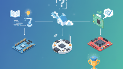
Creating a circuit board is a fundamental skill for electronics enthusiasts. As Dr. Emily Carter, a notable expert in circuit design, once said, "Understanding the basics of circuit boards unlocks creativity in electronics." This highlights the importance of mastering this craft.
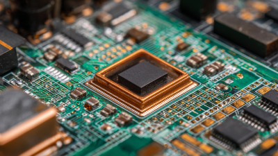
In today's tech-driven world, circuit boards serve as the backbone of countless devices. Designing one can feel overwhelming. Many beginners struggle with layout and component placement. Mistakes often lead to frustration and wasted materials. A poorly designed circuit board may not function, or worse, it could damage components.
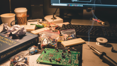
It's crucial to approach circuit board creation with patience. Consider each component’s role carefully. Sometimes, an unexpected design flaw can lead to a breakthrough idea. Embrace the imperfections along the way. Learning from missteps is part of the process. Each attempt brings you closer to a successful circuit board.
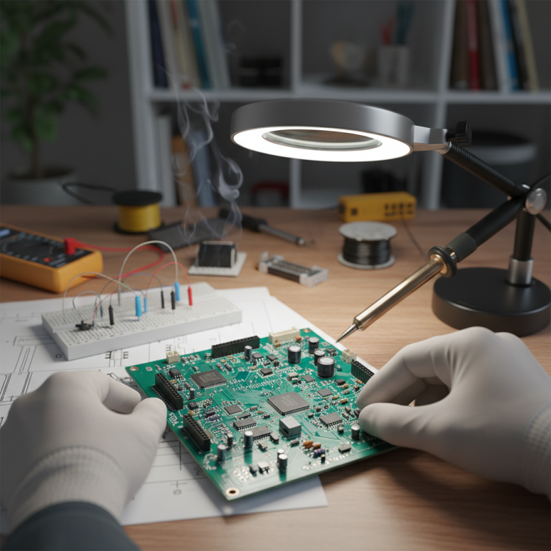
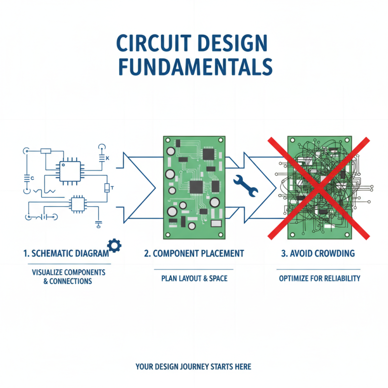
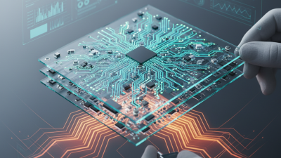
Designing a circuit board requires a solid understanding of its fundamentals. Start with a schematic diagram. This visual tool helps you map components and their connections. It’s crucial to plan out where each part will go. Make sure your components fit within your defined space. A crowded design often leads to issues.
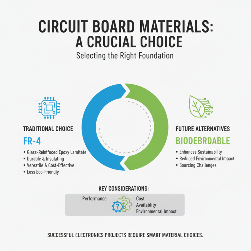
Choosing the right materials is also key. Use a suitable substrate to support your components. Factors like thickness and type affect performance. Test your design before finalizing it. Prototyping can reveal flaws. Sometimes, the layout seems perfect on paper but fails in practice. Make adjustments based on your tests.
Dig deeper into the design software. These tools can be complex and require practice. At first, they might feel overwhelming. Consistent effort will help you create better designs. Reflect on what works and what doesn’t. Learning from mistakes is part of the process. Each project is a chance to improve your skills.
Selecting the right materials for your circuit board is crucial for successful electronics projects. The base material typically used is FR-4, a glass-reinforced epoxy laminate. It is a versatile choice due to its durability and insulation properties. However, it is not always the most eco-friendly option. Exploring alternatives like biodegradable materials may enhance sustainability, but finding reliable sources can be challenging.
Copper is essential for traces on the board. Single-sided boards are common but offer limited design flexibility. Double-sided boards allow for more complex routing but can be harder to manufacture. For beginners, it is tempting to go big, but starting small with simpler designs often yields better results. Inadequate planning can lead to space issues.
The solder mask protects the circuit from environmental damage. Choose between green, blue, or other colors depending on personal preference. Each color may require different curing processes, impacting production time. Reflecting on these choices can help streamline the prototyping process. Many rush this phase, but slow and steady often produces superior outcomes.
Creating a circuit board for your electronics projects can be rewarding yet challenging. Start by sketching your circuit layout on paper. Use basic symbols for components like resistors and capacitors. This helps visualize connections before moving to design software.
Digital tools can streamline your work but don’t rely solely on them. Mistakes can occur, especially with software interfaces.
When designing, pay attention to the spacing between elements. A crowded board can lead to errors. Use clear labels to avoid confusion. It’s easy to overlook small details, but these can have significant impacts. Once your design is ready, print it onto a copper-clad board. Ensure you check the alignment; any misplacement can ruin the entire project.
Soldering components requires a steady hand. It’s common to make mistakes here; components might not sit correctly. Take your time to recheck connections. Once completed, test the circuit. If it doesn’t work, analyze it carefully. Sometimes issues aren’t apparent. Don’t get discouraged; troubleshooting is part of the learning journey.
Each attempt teaches you something new.
Creating a circuit board can be both exciting and challenging. One popular technique for etching your designs is the toner transfer method. In this process, you print your circuit layout onto a special paper using a laser printer. After that, you transfer the toner onto a copper-clad board using heat. This method can be tricky; achieving full toner transfer can require trial and error. The results may vary with different printer settings or paper types.
Another effective technique is chemical etching. Start with a clean copper board, ensuring all grease is removed. You can use a ferric chloride solution for this process. Simply immerse the board in the solution and wait for the desired etching depth. However, the chemical process can be unpredictable. Timing can alter results; too long can lead to damaged traces. Additionally, proper safety precautions are essential when handling chemicals.
Both techniques offer a glimpse into the art of circuit board creation. Every project teaches valuable lessons. Mistakes made while etching can be frustrating. Reflecting on them can lead to better practices in future projects. Enjoy the journey of learning through experimentation.
| Technique | Materials Needed | Estimated Time | Skill Level |
|---|---|---|---|
| Photo Etching | Copper-clad board, photoresist, UV light, developer solution | 2-4 hours | Intermediate |
| Direct PCB Printing | PCB printer, special ink, copper board | 1-2 hours | Beginner |
| Laser Etching | Laser cutter, copper board | 1 hour | Advanced |
| Chemical Etching | Ferric chloride, copper-clad board, protective gear | 1-3 hours | Intermediate |
| Milling | CNC milling machine, copper board, software | 2-5 hours | Advanced |
Testing and troubleshooting your finished circuit board is crucial. Many hobbyists overlook this step, leading to frustration. A survey found that 70% of DIY electronics projects fail due to faulty connections or components. These failures often stem from improper soldering techniques or poor component placement.
Begin by visually inspecting the board. Look for broken traces or cold solder joints. Use a magnifying glass for better accuracy. A multimeter is essential for continuity tests. This tool checks if the electrical pathways are intact. The failure rate can be reduced by 50% with proper testing before powering the circuit.
If the circuit does not work, don’t panic. You may need to revisit your schematic. Sometimes, there's a simple logic error. Check each component for correct orientation, especially polarized parts. Remember, troubleshooting is part of the learning process. Embrace the challenges. Document your findings. This approach helps refine your skills for future projects.